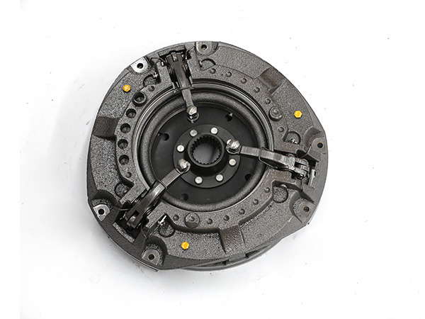
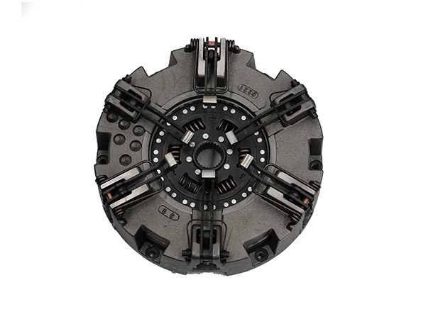
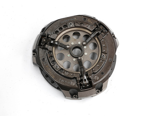
In the design of modern friction clutches, the structure of the tractor clutch assembly and the structure of related components should be reasonably selected according to the category of the tractor model, the use requirements, the matching requirements with the engine, the manufacturing conditions, and the standardization, generalization, and serialization requirements. It is described as follows:
The number of driven discs and the choice of dry and wet

(1)Single-plate dry friction clutch
The single-plate dry friction clutch has a simple structure, easy adjustment, compact axial size, complete separation, small rotational inertia of the follower, good heat dissipation, and smooth engagement even when an axially elastic follower disk is used. Therefore, it is widely used in micro, light and medium tractors and trucks at all levels, and is also popularized in large tractors and heavy trucks with engine torque not greater than 1000N.m. When the torque is higher, a double-plate clutch can be used.
(2) Double-plate dry friction clutch
Compared with the single-plate clutch, due to the increased friction surface, the ability to transmit torque is increased, and the engagement is also smoother and softer; in the case of transmitting the same torque, its radial size is smaller and the pedal force is smaller. However, the axial size is increased and the structure is complicated; the poor ventilation and heat dissipation of the intermediate pressure plate can easily cause overheating and accelerate the wear and tear of the friction plate, and even burn and break; the separation stroke is large, and the separation is not easy to be completely separated if it is improperly adjusted; the rotational inertia of the follower is large and easy to use Difficulty shifting gears etc. It is only used when the transmitted torque is large and the radial dimension is limited.
(3) Multi-disc wet clutch
There are more friction surfaces, and the joint is smoother and softer; the friction plate is immersed in oil to work, and the surface wear is small. However, the separation stroke is large and the separation is not easy to complete, especially when the viscosity of the oil increases in winter: the axial size is large; the rotational inertia of the driven part is large, so it has not been promoted in the past. In recent years, due to the continuous improvement of the technology of multi-plate wet clutches, heavy-duty vehicles are used again, and there is an increasing trend. Because it uses an oil pump to forcibly cool the friction surface, it will not overheat even if it slips for a long time when starting, and the starting performance is good. It is said that its service life can be 5~6 times longer than that of the dry type.
2. Structural type and arrangement of the compression spring

The structural types of the clutch compression spring are: cylindrical coil spring, conical coil spring with rectangular section and diaphragm spring, etc. Arrangements such as circumferential arrangement, central arrangement and oblique arrangement can be adopted. According to the type and arrangement of the compression spring, the clutch is divided into:
(1) Circumferential spring clutch
The compression spring of the peripheral spring clutch is a cylindrical coil spring and is evenly arranged on a circumference. Some heavy-duty vehicles arrange the compression springs on two concentric circles. The circumferential spring clutch has a simple structure and is convenient to manufacture, and has been widely used in various types of automobiles in the past. Due to the increase of the engine speed of the car (the maximum speed is as high as 5000~7000r/min or higher), under the action of the high-speed centrifugal force, the peripheral spring is easy to skew or even seriously bend and bulge out, which significantly reduces the pressing force. The spring ring leans against the positioning seat post, causing serious wear and tear of the contact part or even breakage. Therefore, modern cars and small, light and medium-sized passenger cars mostly use diaphragm spring clutches. But in medium and heavy trucks, the circumferential spring clutch is still widely used.
(2) Center spring clutch
A conical coil spring with a rectangular cross-section or 1~2 cylindrical coil springs are used as the compression spring and are arranged in the clutch contact, so the heat generated by the pressure plate due to friction will not be directly transmitted to the spring and cause its tempering failure. The pressing force of the pressure spring acts on the pressure plate through the lever system, and is enlarged according to the lever ratio, so the spring with a smaller force can obtain enough pressure plate pressing force to make the operation easier. When the central cylindrical coil spring is used, the axial size of the clutch is larger, while the conical spring with a rectangular section can significantly reduce the axial size, but its manufacture is relatively difficult, so the central spring clutch is mostly used in heavy-duty vehicles to reduce its operating force. .
(3) Inclined spring clutch
It is a new type of structure adopted by heavy-duty tractors. A large number of cylindrical coil springs are used as compression springs, which act on the force transmission sleeve at an inclination angle (the angle between the center line of the spring and the center line of the clutch), and the latter pushes the pressure rod and presses the lever ratio. Amplified and applied to the platen. At this time, the axial thrust acting on the inner end of the pressure rod is equal to the axial component of the spring pressure. When the friction plate is worn, the inner end of the pressure rod moves forward with the force transmission sleeve, so that the spring is elongated, the pressure is reduced, the inclination angle is also reduced, and the cos value is increased. In this way, the axial thrust of the compression spring can be kept almost unchanged within the wear range of the friction plate, so that the pressing force of the pressure plate can also be kept almost unchanged. Similarly, when the clutch is disengaged, the force transmission sleeve is moved backward, and the pressing force of the pressure plate is also roughly unchanged. Therefore, compared with the previous two clutches, the inclined spring clutch has the outstanding advantage of very stable working performance. Compared with the circumferential spring clutch, the pedal force can be reduced by about 35%.
(4) Diaphragm spring clutch
The diaphragm spring clutch has many advantages: First, due to the non-linear characteristics of the diaphragm spring, it can be designed so that when the friction plate is worn, the spring pressure can remain almost unchanged, and the pedal force when the clutch is disengaged can be reduced, making the operation light : Secondly, the installation position of the diaphragm spring is symmetrical to the center line of the clutch shaft, so its pressure is actually not affected by centrifugal force, the performance is stable, and the balance is also good: Furthermore, the diaphragm spring itself also acts as a compression spring And the function of the separation lever greatly simplifies the structure of the clutch, reduces the number of parts, reduces the mass and significantly shortens its axial size; in addition, because the diaphragm spring and the pressure plate are in contact with the entire circumference, the pressure distribution is uniform. , The contact of the friction plate is good, the wear is uniform, and it is easy to achieve good heat dissipation and ventilation.
Diaphragm spring clutches have been widely adopted and gradually extended to trucks. A series of diaphragm spring clutches with a transmission torque of 80^2000N.m and a maximum outer diameter of the friction plate of 420mm have been designed and produced abroad, and even some heavy-duty vehicles with a total mass of 2832t also use diaphragm spring clutches. However, the manufacturing cost of diaphragm springs is higher than that of cylindrical coil springs.
The operation of the diaphragm spring clutch used to be a press-type structure. At present, the press-type operation of the diaphragm spring clutch has been replaced by the pull-type operation structure. The latter diaphragm spring is installed in reverse, and the support ring is moved to the vicinity of the big end of the diaphragm spring, which simplifies the structure, reduces the number of parts, and facilitates disassembly and assembly: the stress distribution of the diaphragm spring is also improved, and the maximum stress decreases; the support The ring remains in contact with the diaphragm after wear so that the free travel of the clutch pedal is not affected. In the press-type structure, the wear of the support ring will form a gap and increase the free stroke of the pedal.
3. Structural type of driven disc

The simple driven disc is riveted from the driven disc, the friction disc and the driven disc hub. It has a simple structure and a small mass, and is sometimes used in heavy-duty vehicles, especially in double-disc clutches.
The use of driven discs with torsional dampers is a development trend, which is used in all cars. At this time, the driven piece and the spline hub are connected by a damping spring, which has tangential elasticity to eliminate high-frequency resonance and play a buffering role. Disk-shaped gaskets are installed for elastic clamping and play the role of friction damping, and keep the damping torque stable, so as to absorb part of the energy and attenuate low-frequency vibrations. The torsional shock absorber is specially designed according to the engine and the transmission system and has been corrected by tests, so that the best vibration and noise reduction effect can be obtained. A torsional damper with linear elastic characteristics, the damping spring consists of a set of cylindrical coil springs, commonly used in gasoline engine vehicles. The unevenness of the idle rotation of the diesel engine is large, which will cause the knock between the constantly meshing gears of the transmission. Adopting two or three-stage nonlinear torsional dampers and making the stiffness of the first-stage damping spring group small can alleviate the idling instability of the diesel engine and eliminate the idling noise of the transmission.
In order to make the clutch engagement smooth, the follower plate, especially the follower plate of the single-plate clutch, is generally axially elastic. The easiest way is to open a T-shaped groove on the follower plate, form many fan shapes on the outer edge, and punch them into waves that bend in different directions in turn. The friction plates on both sides are respectively riveted on each other sector-shaped plate. When the clutch is engaged, the driven plate is compressed, and the curved wave-shaped sector is gradually flattened, so that the pressure on the driven plate and the transmitted torque are gradually increased, so the engagement is smooth and soft. This kind of grooving is beneficial to reduce the warpage of the follower piece. The disadvantage is that it is difficult to ensure that the rigidity of each sector-shaped part is exactly the same.
In the split structure, the wave spring sheet and the driven sheet are punched and formed respectively and then riveted together. Since the wave spring sheet is punched by the same die, its stiffness is relatively consistent: since the wave spring uses a thinner steel plate than the driven sheet (the thickness is only 0.7mm), this structure is easy to obtain a smaller moment of inertia, These aspects are superior to monolithic structures. The above two structures, especially the latter one, are mostly used in cars.
A so-called combined follower is often used on trucks. In this structure, the wave spring sheet is riveted on the driven sheet on the side close to the pressure plate, the friction sheet is riveted on the wave spring sheet, and the friction sheet on the flywheel side is directly riveted on the driven sheet. Its moment of inertia is large, but this structure can also be used for large driven pieces that require high rigidity and good shape stability. When the diameter of the truck clutch is less than 380mm, the first two structures can still be used for the follower plate.


